


Engine testing is serious business. There are fuel systems, hot exhaust gases and noise, even before consideration is given to test cells, engine control or the size and weight of the test subject. Digitalization has not replaced physical engine testing, although it has changed the way trials are run. But even as it continues to impact engine testing, some aspects, especially the macro infrastructure required, have remained largely unchanged for decades.
The Arnold Engineering Development Complex (AEDC) is a US Air Force Materiel Command (AFMC) facility located at Arnold Air Force Base in Tennessee. Among the AEDC’s units, the 717th Test Squadron (717 TS) is responsible for propulsion testing. Deputy director of the 717 TS, Adam Moon, teamed with the unit’s technical advisor, Steve Arnold, to answer questions. First, they addressed the role of ground-based engine trials: “Our engine testing does not eliminate the need for flight testing, but it is a crucial and complementary step that reduces the risks and costs of flight
test programs.
“The ground tests we conduct allow engineers to work out the kinks and ensure the engine is safe and reliable before it is ever flown on an aircraft with a pilot.
“A significant portion of our work is dedicated to verifying and validating computer models. The data from performance and operability tests are used to develop, refine and verify the accuracy of computer models that predict engine behavior.
“These models are then used to understand how the engine will perform when installed in the aircraft. Similarly, data from durability tests are used to validate structural design models, ensuring the engine will have a long and reliable service life.
“Ground testing also provides a perfect opportunity to test and validate control system schedules before they are used in flight.”
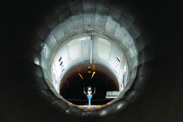
The 717 TS has a range of test cells at its disposal. Arnold and Moon explain: “The original altitude test cells are the turbine cells – T-cells – in the Engine Test Facility [ETF]. They have a 10ft diameter and were designed for testing at conditions below Mach 1.5 and altitudes near 50,000ft.
“The ETF was later expanded with the Ramjet Addition, which includes the J-cells, which are about 20ft in diameter. This expansion increased the testing envelope of the J-cells and T-cells to more than Mach 3.0 and altitudes above 75,000ft.”
The Aeropropulsion Systems Test Facility (ASTF) was added in the 1980s and features two 28ft-wide C-cells which are the largest test cells within the 717 TS. The ASTF has a similar flight envelope to the ETF but with more than double the airflow capacity. The choice of test cell often depends on the physical size of the engine.
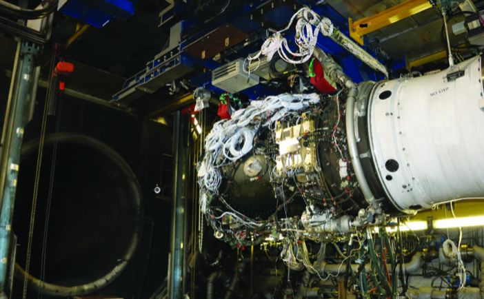
(Photo: US Air Force photo / Deidre Ortiz)
Hot & Dusty
While the AEDC’s primary tasking is military, it also supports external trials on commercial engines.
Rolls-Royce is among the customers using its high-altitude capabilities, although the company handles most of its testing in-house at its Testbed 80 facility in Derby, UK. Pat Hilton, manufacturing manager – engines and test at Rolls-Royce, describes Testbed 80 as “the biggest and smartest testbed in the world”. It routinely conducts powerful full engine x-ray tests and offers scope for ingestion, hail, rain, dust and blade containment testing.
Hilton says it is not so much the capability as how it is used that makes Testbed 80 stand out. “When we wanted to test our Trent XWB-97 engine to improve its durability in hot and dusty conditions we were able to replicate the exact conditions of the Middle East, gathered from our engines operating in that region, instead of using synthesized data,” he says.
Testbed 80 conducts its testing at sea level in ambient conditions. Rolls-Royce has traditionally used a flying testbed for altitude testing but recently retired its dedicated Boeing 747. “When we next need to conduct a campaign at altitude we review the options with our partners and agree a strategy that could combine flight testing, ground-based altitude test facilities and virtual testing using multi-physics models,” Hilton explains.
The emphasis at MTU Aero Engines is on testing engines and engine components. Company expert Tim Haas says, “At MTU we mainly develop high-pressure compressors and low-pressure turbines, which require very different test profiles, test setups and testbeds. We test high-pressure compressors in our Munich test facility, driving the compressor with a powerful electric drive motor and moving air through it.
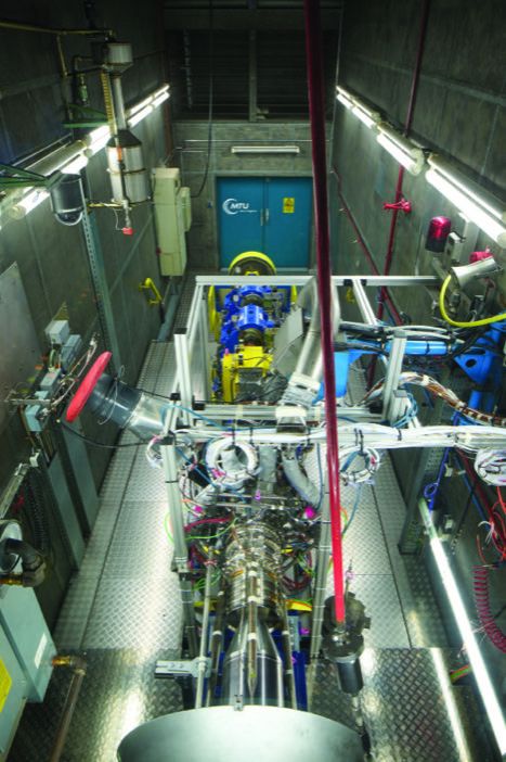
“The drive unit is used to control compressor speed, allowing us to set steady-state operating points and test transient behaviors. We do that under idealized conditions to get an idea of the component’s efficiency. We also examine stability, reducing airflow at the back end of the compressor to bring it close to the stall line, allowing us to check our predictions of its performance. After the test, we calibrate our prediction to the measured data to improve our analytical methodologies.”
Haas says there is a common misconception around low-pressure turbine trials, which are expected to involve high temperatures. Testing the turbine in isolation, as a standalone module, is essential to simulate the aerodynamic conditions found in the complete engine and for that, an altitude test facility at the University of Stuttgart is used. “It allows us to adjust the inlet temperature and pressure to similar or equal aerodynamic conditions to those in the engine. That usually means inlet temperatures of a few hundred degrees,” he says. “Then, since there is expansion through the turbine, the temperature behind it is ambient.
“We use a closed-loop altitude test facility, moving air in a loop through the turbine and using a water brake to control the turbine’s speed and extract its power. The facility enables us to adjust air temperatures and pressures to match every flight condition, so we can understand the component’s aerodynamic behavior across the entire envelope.”
At the AEDC, Arnold and Moon reveal the tried and tested method used to simulate high-altitude conditions: “We use a series of powerful exhaust compressors. Either centrifugal or axial, they reduce pressure inside the test chamber to match the desired altitude pressure. They can be configured in parallel for low-altitude, high-mass-flow conditions, or in series for higher-altitude simulations.
“The fundamental technology of using exhaust compressors to simulate altitude has remained largely unchanged for about 75 years. However, we continue to explore and implement new technologies for controlling these systems more precisely.”
S1MA and RISE
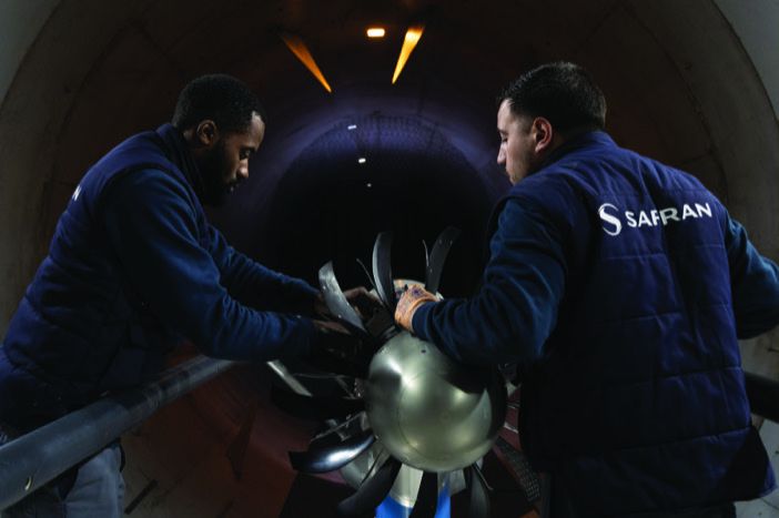
ONERA (the Office National d’Études et de Recherches Aérospatiales – the French national aerospace research laboratory) has been testing the CFM International RISE open-rotor engine in its wind tunnels. The work includes trials simulating cruise conditions at altitude.
Marie José Martinez, director of ONERA Wind Tunnels explains the simulation environment: “From an aerodynamics standpoint, two parameters need to be reproduced in the wind tunnel to simulate
actual flight conditions – the Mach number and the Reynolds number.
“The Mach number at which the fan and stator blades operate is reproduced by setting the speed of the flow in the wind tunnel test section – by adjusting the hydraulic power transmitted to the wind tunnel fans – and the model fan rotation speed.
“In our S1MA wind tunnel, the world’s largest sonic wind tunnel, the flight Mach number can be replicated with a very high accuracy of better than 0.1% and the Reynolds number, although smaller than in actual flight conditions, is kept close to it thanks to pressure and density in the wind tunnel being higher than in flight, compensating for the effect of the scale model test subject, which is around 1:5.
“Humidity is controlled during the test so that it does not affect the aerodynamic forces.”
The RISE (Revolutionary Innovation for Sustainable Engines) program places ONERA and its test facilities at the forefront of next-generation engine design. Reciprocating, or piston engine technology on the other hand drove the first sustained powered and controlled flight in 1903 and continues to evolve.
But, when aerospace technologies change there is always a requirement for trials. The University of Wisconsin-Madison Engine Research Center operates a facility that is dedicated to the testing of small- to medium-sized piston engines with power outputs up to 350kW.
The work includes environmental and altitude simulations and David Rothamer, director of the engine research center, explains how ambient conditions are created in the test cell: “We test complete piston engines with their normal intake system and exhaust manifold, which connect to our facility. Pressure, humidity and temperature conditions at the engine inlet are simulated to match those at altitude and the exhaust back pressure also mimics altitude conditions. We are currently upgrading the system to control the air temperature coming from the turbocharger compressor to match conditions that would be present at altitude.
“The facility occupies part of five rooms. The air handling unit that conditions the humidity and air temperature occupies most of one room. A chiller that sends glycol used to cool the air, along with a coolant conditioning and oil conditioning skid are in a neighboring room. A large liquid ring vacuum pump, along with a large, variable area cage valve enables the low pressures present at altitude to be simulated.”
Speed and size
The scope of the AEDC’s testing includes small turbojets for missiles, through afterburning military engines and ramjets, to high-bypass airliner turbofans. “The testing requirements for different types of engines vary,” says Arnold and Moon. “For instance, military engines typically undergo more extensive operability testing, including the use of distortion screens to simulate challenging flight conditions.
“Afterburning military engines that operate at high Mach numbers may require additional durability testing under the stress of elevated inlet pressures
and temperatures.
“The main difference between testing small and large engines lies in the facility and test article integration. Large high-bypass airliner turbofans for example, have more complex controls and service requirements, including power extraction and heat rejection, compared to a small turbojet for a missile. Although the test objectives might be similar, the choice of test cell is also a factor. Smaller engines are often tested in the smaller, more cost-effective T-cells, while larger engines require the J-cells or C-cells.”
Ramjet propulsion systems operate best at high speed, typically Mach 3 and above, potentially posing a test challenge. Arnold and Moon reveal that the AEDC does not achieve the conditions required in quite the expected way. “A high-speed wind tunnel is not used in the way one might think. Instead of placing the entire ramjet in a supersonic free-stream, we utilize adirect-connect test approach. In this setup, the ramjet inlet is directly connected to a plenum that supplies conditioned air.
“To simulate the high-speed flight conditions a ramjet requires, our facilities can either use a freejet nozzle to generate a localized supersonic flow at the ramjet’s inlet, or they can provide air at the temperature and pressure that the ramjet would experience after the air has passed through its inlet’s shockwave system. This method is more efficient since it bypasses the need to accelerate a large volume of air to supersonic speeds. These tests are conducted in facilities like the J-cells, which were specifically added for ramjet testing.”
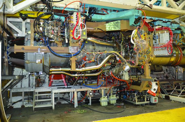
(Photo: US Air Force)
In the final analysis, engine trials are all about data gathering across a range of altitudes and conditions. Arnold and Moon place the AEDC’s work into three broad categories that neatly summarize most engine trials: performance, operability and durability tests.
Performance tests are conducted under steady flight conditions to accurately measure key engine parameters including thrust, airflow and fuel flow, as well as internal engine pressures and temperatures to evaluate component performance. Operability tests involve transient maneuvers to ensure stable engine operation under potential upset conditions, such as preventing compressor stalls or combustor blow-outs, and durability tests subject engines to extreme conditions of temperature or pressure to ensure they meet their expected service life.
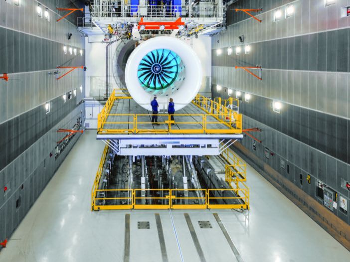
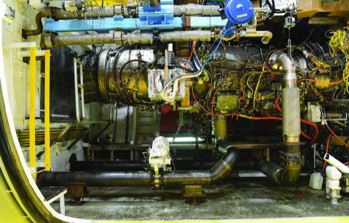
(Photo: Rolls-Royce)
These and other trials are the bread and butter of Testbed 80’s work, which can gather data on more than 10,000 engine parameters. With so much data coming from a trial, Rolls-Royce is driving not only the test in hand, but also future developments, as Hilton reveals: “We use real-time data for executing the tests to the correct conditions and gather huge amounts of data for our engineers to interrogate to satisfy them that the experiments we undertake are accurate. And then we feed data into the brain of our engineering and design organization, for the creation of digital twins and future product design.”


