


X-ray computed tomography (CT) has successfully entered the field of coordinate metrology as a flexible non-contact measurement technology for performing dimensional measurements on industrial parts.
CT provides several advantages compared to conventional tactile and optical coordinate measuring machines (CMMs) and lets engineers perform non-destructive measurement tasks that are often impossible with any other measurement technologies. For example, the inspection of complex and high-value additive manufacturing products with high density of information and without any need to cut or destroy the components.
In aerospace, CT can be used to inspect smaller to medium sized components such as turbine blades, aluminum castings and tube welds. With CT, quantitative analyses can be performed at several stages of the different products cycles, enabling the optimization of products and manufacturing processes and the evaluation of conformity to product specifications.
How CT works
The three main components of an x-ray CT system are the x-ray source, rotary table and detector. Different CT system configurations exist: for example, flat panel detectors (DDA) or linear diode array detectors (LDA) can be used.
With LDAs the phenomenon of x-rays scattering, relevant while scanning high density materials as in aerospace applications, does not impact the scan. However longer scanning times are required.
The x-ray source-to-detector distance and x-ray source-to-object distance define the geometrical magnification of the CT scan and the voxel size of the 3D CT model of the part. The use of variable X-ray source-to-detector distances, as offered in the NSI system portfolio, is also fundamental for aerospace applications to achieve the best signal possible.
CT technology is based on x-ray’s attenuation principles. The size and the thickness of the part and the material density therefore plays a fundamental role in its effective use. The larger the component and the denser the material, the more power is required for the x-rays to penetrate.
The output of a CT scan is a 3D model of the part, upon which it is possible to perform very accurate measurements without any form of contact or need to cut or destroy the part. CT also allows for material inspection and identification of internal defects such as voids, cracks, etc. When inspecting composite materials, CT can also be used to identify delaminations.
Examples of CT use
The image below shows an example of wall thickness analysis and measurement of multiple dimensional features on a turbine blade.
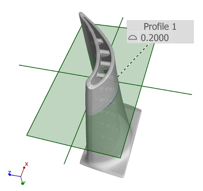
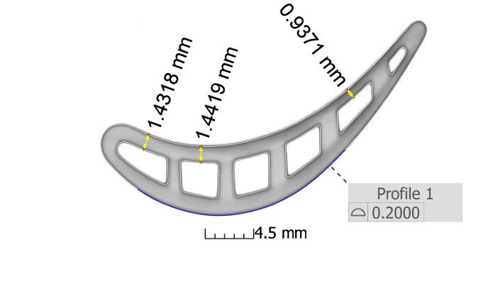
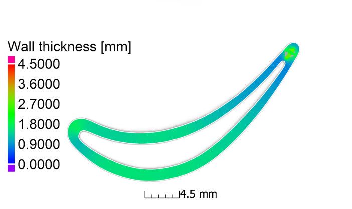
Figure 1 (a) represents the 3D model of the blade which can be entirely navigated through user defined clipping planes. Figure 1 (b) shows how it is possible to measure internal features as well as check the conformity of the airfoil profile to the specifications. In Figure 1 (c) an example of wall thickness analysis is shown.
Figure 2 below is an example of porosity analysis on a tube weld.
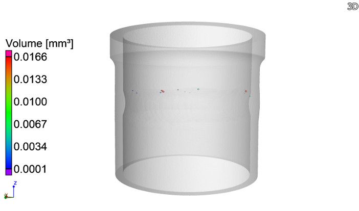
In this case the color bar represents the different pore sizes, which are also visible on the 3D CT model.
CT offers the capability to locate the porosities in the 3D model of the part and to provide information on the different porosities’ volumes. The size of the porosities or defects that can be detected depends on the scan resolution, which is also a function of the part size, geometry and material. Advanced scanning techniques such as NSI Subpix allow the engineer to achieve an improved resolution and therefore a larger field of view for a given resolution.
Other CT applications include nominal/actual comparisons in which the volumetric model of the actual part is registered and compared to its nominal model, usually the CAD model, and fiber analysis for composite materials.
Advantages and considerations
Compared to conventional measurement technologies CT provides a wide series of advantages, including the ability to perform measurements of the component on complex and/or non-accessible features in a non-contact and non-destructive way, and with high density of information.
In aerospace applications this is fundamental because of the often high cost of the parts, which does not allow for destructive testing. CT also lets engineers quickly evaluate the conformance of parts before high-cost machining processes.
When measuring for example the freeform surfaces of turbine blades CT can provide a high density of points in a shorter amount of time than conventional tactile CMMs, and being a non-contact technique there is no need for probe tip compensation when inspecting free form surfaces.
Fundamental factors to be considered when using CT include the achievable geometrical magnification which depends on the part size and geometry, the part material and thickness.
 This article was written by Valentina Aloisi, metrology product innovation manager at North Star Imaging.
Valentina has a PhD in mechanical engineering from the University of Padova, Italy, where her studies focused on industrial computed tomography.
Her background is in production engineering and industrial metrology, she holds a CMTrain – Level 2: CMM – Operator certification and h is the author of several peer-reviewed journal papers and conference papers on computed tomography and metrology. She has also co-authored a book chapter on computed tomography and has presented her research contributions at major conferences and symposia in Europe and the USA.


