


The need for greater speed and efficiency in the aerospace sector has precipitated a technical evolution which is driving the increased electrification of aircraft sub-systems. This is especially the case when it comes to components such as fuel pumps. Previously often driven from main shaft of the jet engine, the more common practice these days is to use a stand-alone motor to drive them. This eliminates the need for a gearbox to manage the speed at which the fuel pump is required to operate.
This practice is being increasingly applied with other sub-system components too. While this brings a clear benefit in terms of reduced weight, the use of high-speed motors in these applications comes with its own challenges when it comes to the testing of components.
Testing requirements intensify
The requirement for these sub-systems to operate at ever higher speeds itself creates a need for higher-speed component testing capabilities which are more reliable and can offer greater versatility than current ground-based testing equipment. This process needs to verify that the performance characteristics of all components being tested – known as Units Under Test (UUTs) – meet their specification.
Testing typically examines factors such as the amount of torque a UUT demands to operate at a given condition; efficiency; wear; and operating parameters at given conditions, such as the extremes of cold at which many components will have to operate.
In the case of fuel pumps, for example, testing must validate whether the pump displaces the correct flow and pressure at high speed. A further requirement for fuel pumps, and other components, is for the testing process to be safe even when components are operating in fuel-rich environments.
Meanwhile, with manufacturers constantly examining new ways to cool UUTs at the higher speed at which they are being tested – bespoke oil circuits, hydrogen and liquid nitrogen cooling systems are now all seeing service – additional demands are placed on the flexibility of testing technologies.
A number of options have generally been available to Tier 1 and 2 component manufacturers and suppliers seeking to undertake this type of testing prior to certificating and supplying components to airframers.
The most common is the use of a driveline incorporating speed-increasing gearboxes. This method of testing has become highly popular over the years, but some gearboxes have – literally – struggled to keep pace with the burgeoning demands being made on the testing process.
Many existing systems can only operate at up to around 8,000–10,000rpm, although some can achieve circa 30,000rpm. However, given the higher speed requirement – with typical operating speeds of up to 40 – 50,000rpm, and even beyond, now not uncommon – these systems cannot provide the required guarantee of performance of the UUT.
Accuracy concerns
Meanwhile their accuracy can also be open to question, especially at higher speeds. A key reason for this is that testing at high speed necessarily requires the presence of lubricant to cool both the gearbox and the UUT.
Any leakage of the lubricant has the potential to adulterate the testing process and render its result invalid. Leakage of this kind is more likely to result in a ‘fail’ against either in-house parameters, or official regulations governing performance. And this may occur even if there is nothing wrong with the component at all – resulting in either disposal of the part, or time wasted on investigation into what could be wrong – to say nothing of the cost of making a new component.
Our own engineers saw one application where as many as one in eight units was ‘failing’ even thought it was later identified that there was no issue with the manufacturing process.
Meanwhile, constant operation at high speeds and temperatures means gearboxes of this kind can often require lengthy and costly maintenance, to counter issues such as bearing wear and failure. This can necessitate their removal from the testing rig – a process taking many hours, if not days – and the installation of a replacement gearbox, again taking up valuable time, if testing is not to be further interrupted. On top of that there is the need to have a replacement unit – or even several – on hand, tying up cash in capital goods.
Motor-based alternatives
Another option for testers is to use motor-based testing systems. However, these come with their own limitations around speed, capacity and reliability, as well as potentially extremely high cost. Motors for these applications can typically only operate at up to around 20,000rpm – again well below the level required some tests, and certainly therefore not a ‘future-proof’ solution. Faster motors tend to be those that are lower-rated for power, with the few available products of this kind being very expensive, even before the costs of necessary ancillary equipment such as a suitable drive system and variable frequency drive (VFD) are considered. These systems also typically need integrated chilled water cooling to operate safely and effectively, adding further expense to this option.
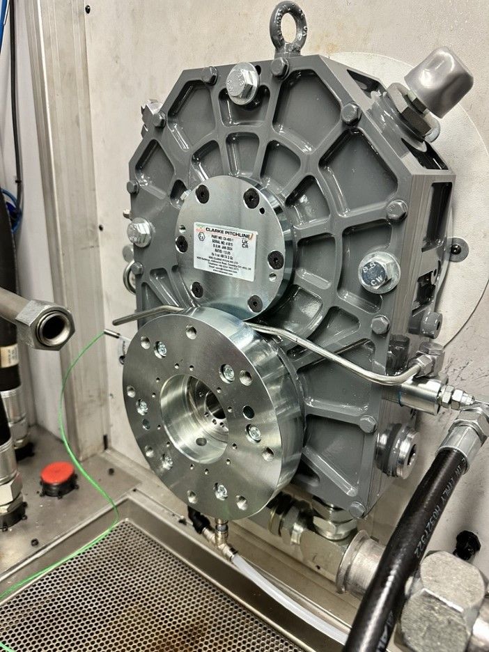
The limitations with existing systems have driven leading players in the field of compact, high-performance gearbox manufacture to examine and develop new, modular gearbox options which can meet the need for robust, versatile and accurate high-speed testing.
Suitable for either foot or flange mounting, these gearboxes can be supplied as stand-alone units or within a complete drive system package, also including a motor, VFD and couplings, allowing or ready integration into existing test rigs.
Other benefits
Advances in sealing technology have enabled the development of proprietary technology which negates the possibility of lubricant leakage, meaning test results are reliable. Accuracy is also ensured through the use of special heat treatment on gears, with optimized geometries – DIN3 or even better is now readily achievable – as well as optimized bearing technology, allowing testing speeds of up to 55,000rpm and so enabling them to act as a truly future-proof solution as required operating speeds – and therefore testing speeds – continue to increase.
These systems require minimal maintenance other than an overhaul every three years or so, with an integrated cloud-based monitoring system advising when any maintenance is needed, allowing for flexible scheduling. They are also ATEX compliant, guaranteeing their safety for use in fuel-rich environments, particularly when components such as fuel pumps are being tested. And their versatility allows them to work without disruption irrespective of the cooling system in place.
Furthermore, as completely modular systems, there is the option for testers to effectively specify their own testing unit to incorporate, for example, high-accuracy, high-speed torque meter measurement modules and torque overload protection modules.
Perhaps most importantly of all, the accuracy achievable is down to ±0.05% – typically 50% better than that of other systems currently available.
Such systems are now seeing regular service in Tier 1 testing facilities for components as varied as fuel pumps, generators, permanent magnetic alternators (PMAs) and high-speed motors – delivering highly accurate and rapid test results in both R&D and product acceptance testing applications.


