by Jack Roper
Aircraft fatigue is older than aviation itself. The Wright Brothers’ first powered flight was delayed by a fatigue crack in a hollow propeller-shaft, while engineers first identified fatigue in train-axles in the early 1800s.
Fatigue is when microscopic cracks in metal grow over time to a critical size, then propagate rapidly and cause structural failure. This understanding of fatigue stems from the de Havilland Comet failures in the 1950s and informs several aspects of modern aircraft design.
“As the first jet airliner the Comet introduced many concepts,” says Dr Andrew Halfpenny, director of fatigue analysis company nCode. “But behind revolutionary changes lurked problems.”
Stress-concentration at square, incorrectly riveted window-corners caused the Comet airliner Yoke Peter’s 1954 explosive decompression. The first aircraft fatigue test confirmed this by cyclically pressuring an identical Comet’s fuselage for five months in a water-bath.
“Today’s metal thicknesses, rivet-spacing and bonding were all learned from the Comet,” says Halfpenny. “What was learned was shared.”
Tensile failure is when load exceeds ultimate material strength and is comparatively predictable. But fatigue failures are a result of fluctuating load-cycles.
“Over time, materials seem to tire, breaking at loads well below their tensile strength,” says Halfpenny. “The other problem is scatter – across 100 production-line components, there’s at least a factor of two between the first and final failure.”
Limiting failure
In the 1850s, German engineer August Wöhler conducted the first fatigue tests, applying loads to railway axles.
“Wöhler created a fatigue strength, below which axles seemed to last forever,” Halfpenny says. “If loads exceeded it, they would break – not immediately, but in time.”
Wöhler Curves plot failures on axes of stress amplitude against the number of cycles: if stresses remain in a safe region below the curve, a material never fails. But aircraft capable of flight must be designed within a finite region of widely-distributed failures.
Embryonic cracks form at riveted joints when persistent slip bands in micron-sized metallic grains slide inwards. They grow at 45° to loading, crossing perhaps five grain-boundaries. “Then they change direction and grow perpendicular to applied load,” says Halfpenny. “The crack-tip has created a stress-concentration, which then takes over and drives out fatigue to the point of failure.”
This microscopic behavior explains the unpredictable scatter of failures in identical specimens. Halfpenny says, “Millions of tiny sliding cracks may never have the energy to cross a grain-boundary. It just takes an extra yank at the right time.”
Crack growth-rates vary between materials. Undercarriage structures are prone to sudden, brittle failure. “Steel offers strength but can’t absorb plasticity,” says Halfpenny “When cracks appear, they quickly grow to failure.
“But soft, ductile fuselage materials like titanium absorb plastic loads. Stress flows around cracks and finds an alternate load-path.
“Cracks grow steadily and the titanium fuselage is still fine.”
Growth-rates inform different design-life philosophies. Fuselages are designed to be as damage-tolerant as possible.
“We design undercarriages for safe life periods then retire and replace them. We accept that cracks exist and live with them, otherwise we would change fuselages every year,” Halfpenny says.
Coupons to full-scale

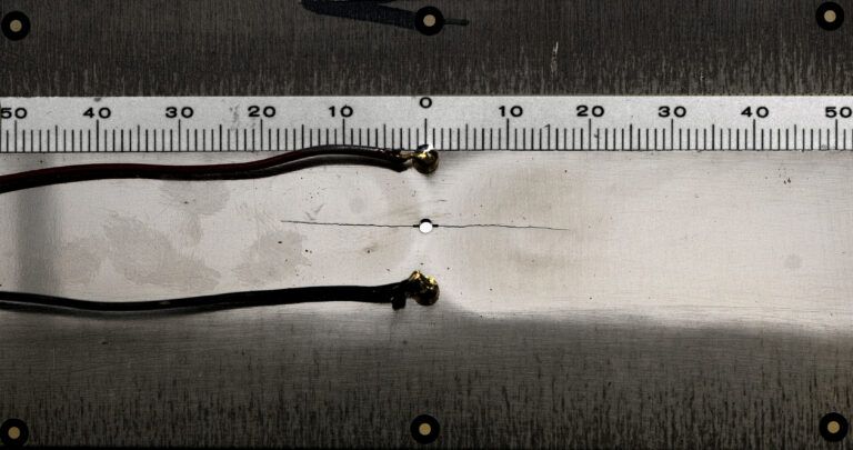
Fatigue testing focuses on showing how cracks grow over time, so inspection intervals can be planned and cracks spotted and repaired before they result in failure. Perhaps counter intuitively, cracks are often repaired by drilling holes to disperse crack-tip stress-concentrations.
During development, data from single-axis coupon tests establishes material strengths and is used to parameterize models. Traditionally, an aircraft’s qualification culminates in full-scale airframe testing, where engineers apply deliberate damage to see how quickly cracks become detectable then grow.
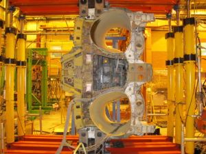
“Complex tests use many hydraulic actuators to mimic an expected lifetime of load-cycles,” says Marcel Bos of the Royal Netherlands Aerospace Centre (NLR) and general secretary of ICAF (International Committee on Aeronautical Fatigue and Structural Integrity). “Fatigue isn’t calendar-related, so it’s feasible to mimic many years in months.”
“An aircraft’s structure is designed to be damage-tolerant and you will solve problems during the test. Developing suitable repairs is essential preparation for the aircraft’s operational service.
“The beauty of fatigue is it often appears as striations on crack surfaces,” continues Bos. “An innovation is the use of marker-loads in test spectra. After a test, we break cracks open to find indications of growth under an electron microscope.”
Like rings in a tree, striations chronicle repeated load-cycles. Applying an unusual pattern of loads every so-many cycles during a fatigue test creates a pronounced striation. Engineers use this to provide a temporal marker in post-test investigation.
Advanced software and controllers facilitate complicated multi-axis tests. “Old-fashioned coupon testing involved handwork – stopping the machine and measuring cracks,” says NLR test house director, Paul Arendsen.
Today, crack-growth is inferred from increases in a specimen’s electrical resistance. “Tests run 24/7 with automated measurements and photography,” says Arendsen. “Not just elastic testing: it’s kinematically-controlled system-testing with many movements and angles of elevation.”
Virtual testing
Increasingly, designs are tested virtually in simulations using finite element models. Physical tests parameterize, refine and validate the models. “I’m a hardware guy and I’m not afraid for my job,” says Arendsen. “Confirming models means plenty of physical testing has to be done.” Design models can furnish digital twins with data, which enable prognostic monitoring of aircraft in service. NCode’s DesignLife software optimizes fatigue life through simulation.
“We take lots from flight-profiles, Wöhler Curves from coupon tests and geometries from finite element models,” Halfpenny says. “We run a simulation with the loads, materials and aircraft geometry, find the stresses and predict the life. Designers can tune that life by changing the geometry.”
Building and testing a prototype then validates the analysis used for design. “We can’t model down to the granular structure, so we treat that statistically. Our maths works brilliantly for metal airplanes,” Halfpenny says.
“But the use of composites returns us to the days of the Comet, before computers. Carbon fiber is strong in tension but buckles under compression, so we reinforce it with a matrix.”
In carbon fiber, failure modes interact. Cracks first spread through the matrix, which delaminates from the main fibers, which themselves then begin to fracture.
“We’re having to start over with simulations and with treating composites statistically,” says Halfpenny.
“Metal has uniform properties in every direction. But every square centimeter of a composite aircraft can have different mechanical properties.”
Innovation
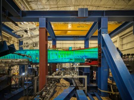
Engineers are working hard to solve the fatigue challenges posed by composites. One such solution has been developed by the Defence Science and Technology Group (DSTG) at Australia’s Department of Defence, which has developed a novel means to obtain full-field stress imagery in fatigue tests.
“We use the observed physical behavior of airframes to validate structural models,” says the DSTG’s
group leader for material state awareness, Dr Nik Rajic. “Our primary instrument is the electrical resistance strain-gauge, which provides isolated point-measurements of strain.”
Thermoelastic stress analysis is used to measure changes in a material’s temperature under tensile or compressive loads. Capturing temperature fluctuations indicative of stress demands 1mK-level sensitivity. Traditionally this has been achieved with photonic cameras directly detecting photons emitted by an object. Photon detectors are highly sensitive but unfortunately require extreme cooling and are cumbersome and expensive.
In contrast, microbolometers are temperature-dependent resistors that respond to incoming infrared energy. Microbolometer cameras don’t require cooling, making them smaller, cheaper and more rugged. However they are markedly inferior to photonic cameras in terms of raw image quality.
“But a quirk of noise morphology makes our image-processing particularly effective in eliminating noise from microbolometers,” says Rajic. “We process the image-sequence synchronously with an actuator, transducer or accelerometer signal which describes the structural loading. We find components of the temperature response which relate closely with that load-signal.”
This process drops the noise-floor of microbolometer imagery to 1mK, well below a photonic camera’s ~15mK noise floor. Rajic’s team have proven the technology in the industrial environment of the F-35 structural test program.
“Our technology provided unvarnished truth about stress distributions in complex airframe structures, allowing models to be tuned to physical reality,” says Rajic. “We quickly obtained information simply unavailable with other sensors.”
Real-life effects
Certification assumes expected aircraft usage, but fatigue stems from actual use. The Aloha Airlines 737 flight that failed catastrophically in 1988 was certified for 75,000 ground-air-ground cycles. But it had done 89,000 because of the nature of its island-hopping journeys. Usage is influenced by airspace.
Such variations in real-life usage make in-service inspection vital. “Aircraft undergo visual inspection about every 600 hours, or three to six months,” says senior lecturer in aviation technology at Australia’s University of New South Wales, Dr Graham Wild. “It’s mostly done by eye, but micrometer-sized cracking underneath paint is difficult to see.”
Structural health monitoring (SHM) aims to eliminate human error with automated on-board diagnostics using various techniques and sensors. Wild says, “SHM tracks cracks, corrosion, pressure, temperature and in space, micrometeorites and radiation impact.”
SHM systems can use piezoresistive strain-gauges to monitor bending-loads on wings, probes to monitor corrosion in engine bays, sensors to detect pressure changes where cracks admit air and acoustic sensors. FBG (fiber Bragg grating) sensors are also being used in aircraft to detect changes in sound, vibration and temperature within aircraft and their components. Machine learning pinpoints microscopic cracking amid a flight’s prevailing din.
Wild says, “We listen to micro-cracks with microphones that use the same laser interferometry as gravity-wave detectors, the most sensitive instruments available.
“Operational noise is omnidirectional, but damage starts in one place,” says Wild. “We use a microphone array to detect signals from a specific direction.”
Much was learnt quickly about metal fatigue from the de Havilland Comet’s failure. A similar need to expand knowledge about fatigue behavior in composites exists today. But some question if progress is hindered by today’s culture of IP protection and litigation.
Halfpenny says, “Back then, it was command-and-control. The Comet’s chief designer was notoriously bad-tempered about news he didn’t want to hear. But, success is a function of both engineering and corporate culture. Today there’s better internal communication – engineers can talk to their boss.”


